Freitag, 15. Juli 2011

DIY Flexible Circuits

I am currently creating flexible circuits for a project I am working on. How to create your own flexible circuit is well documented:
http://www.instructables.com/id/DIY-Flexible-Printed-Circuits/#step1

The etching instructions I followed can be found here:
http://www.instructables.com/id/Stop-using-Ferric-Chloride-etchant!--A-better-etc/

For my project however I need multiple layers and I also need to integrate several IC's with many small pins. First I figured I would have to get it printed profesionally, however I ended up giving it a shot, with surprisingly good results.

Flexible Circutis & IC's

To test whether this was feasable I decided to create small brakout boards for a multiplexer and an atmega. I managed to get a friend interested in this, so together with Marty I designed some simple 1 to 1 pin breakouts for the two ICs.


Here you can see the two circuits printed on pyralux using a solid state printer. I designed them using Inkscape (http://inkscape.org) a freewhere program which turned out astoundingly powerful and userfriendly.
Below are two images from the etching process.


Once out of the etching solution and cleaned we went about soldering the components.  Neither of us had any Idea on how to actually do this, however this sparkfun tutorial gave me some confidence that it was actually possible: http://www.sparkfun.com/tutorials/36


This is what I learned:

- make sure that your circuit design and the IC line up perfectly. When designing your circuit make sure that the footprint is as close to the actual area touched by the feet of the IC. Making them a lot bigger or smaller would make it a lot more difficult to solder.

- make the leads as thick as possible. If they are thinner than 1mm they are very easy to tear off the plastic base.

- tin the connecting elements and some of the surrounding circuitry. Cover it in a thin layer of solder

- glue the circuit in place. We used spray glue. You can use any glue, but make sure that it does not push the circuit up. We first tried a crumbled bit of scotch tape, but that messed things up badly. Ideally the circuit should be glued down well enough to connect the circuit even without soldering.

- very quickly push the feet down with a HOT soldering iron. If the iron is hot enough, the connecting leads will heat up and the solder will flow toward the feet of your IC. You dont need a lot of solder to make a connection. If the iron is not hot enough, this does not work and it gets messy.

- once all your feet are connected in a satisfying manner use soldering wick (http://www.sparkfun.com/products/8775) to clean it all up a bit. If you have solder bridges it is usually sufficient to place it on the lead near the bridge, the solder will then flow towards the lead. In theory, once you have connected the IC to the circuit you never have to bring it back in contact with the soldering iron, minimizing your risk of burning it up


Once all that was done I soldered on some pinheaders and stuck the whole thing in a breadboard:


To make sure that I did not fry anything, I compared it to the breakoutboard by sparkfun


Aside from the fact that our little board is transparent, flexible and just overall more charming and lovable than the sparkfun version it performed identically. I think it might have been slightly noiser, but that could also just have been me not believing that it would perform equally well....


Multi-Layerd Flexible Circuits
This was surprisingly simple. To connect a small matrix of sensors I simply designed the layers seperatly. Then I made holes in the top when where they where required and soldered in the sensors. Kaboom. Magic :-D
 top layer with holes

 bottom layer

both layers together

both layers with sensors mounted
Anyway. Thats it for now. I will be working on this stuff for a while now and will report back with any further insights I might have. While I am doing so - does anyone have any further suggestions? Any secret tricks you use when creating your circuits?
Anyway
Thats it for now.
Cheers
p. 


.

Sonntag, 26. Juni 2011

Ribbon Cables - Arduino Cable Management


EDIT: For the record: DONT do this. Unless you are on a super, super, super tight budget, buy these:
http://www.pololu.com/catalog/category/71
together with these:
http://www.pololu.com/catalog/category/70

Seriously. Make life soooo much easyer.

************************


I stumbled across John Liu's Phi Connect and loved everything about it, except that he doesnt have an Arduino Mega version.

check it out: http://liudr.wordpress.com/gadget/phi-connect/


*

I am prototyping a lot with the Arduino Mega at the moment, and I wanted to improve my cable management, so this is what I came up with.


I have 24 leads connected. 8 go to analog in 0 - 15, 4 go to digital 2 - 7 (as I dont use pin 0 & 1 anyway...) which leaves me with a power and ground cable. works very nicely for me, especially as my actual application has to be semi-independent of the arduino.

If anyone plans on doing this for themselves, here is how I ended up doing it.

a) Prepare the wire
 See how the ends are sort of round? Thats annoying when soldering.

Cut them straight.  Actually, this still did not work 100% next time I want the outside leads to be slightly longer than the inside ones...


After crimping them, I put a ton of solder on both the cable and the pinheader.

Soldering the pinheader is a real pain. The stuff just wont stick to it, and if you fool around too much you start melting the plastic and the pins get loose/crooked etc.


Its inportant however, becouse once thats done, you can just push them together with your soldering iron. Your other hand will be free, as you dont need to add anymore soder, so you can use it to make sure the cable and the headers line up perfectly. If you bend the cable in the right shape, and apply the right amount of solder beforehand you can solder several leads at the same time... after doing this a couple of times you learn how to do it quite efficiantly.

Once it was done I made sure that there where no connections between the cables, wrapped it up with electrical tape and thats all there is to it.


It was more work than I had anticipated ... but assuming they last me for a while, its definitifly worth it.

Mittwoch, 1. Juni 2011

Underwater IR Webcam

So Connor and I set out to waterproof a webcam the other day...

We decided to just coat the whole thing in a thick layer of silicone, this basically is just a test for a future project we plan on doing.

It worked out fairly well, though no long term underwater testing has been done yet...


Here, our beautiful workspace:


After coating it with silicone we got this wierd artifact (the semi-circle in the top right corner). If anyone could shed any light on why this appeard, I'd love to hear it:


The "finished" IR underwater Webcam:

Freitag, 27. Mai 2011

Flex Sensors by Flexpoint

I have just been playing around with some sensors by Flexpoint. And I have to say, that I really love them...


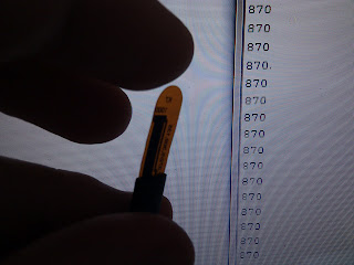
While the company appears to focus on custom design, they produce standard sensors in three sizes, 3", 2" and 1". The actual variable resistor within the sensor is a bit shorter. Check the image for approximate actual measures:


Other flex sensors I had previously worked with where quite noisy and corse. Also they where usually pressure sensitive as well which in some cases can confuse readings. Another thing which I was sort of afraid of was that they had some type of memory, similar to the conductive polymere I have been working with.

I started playing with the three inch sensor. This is what I figured out:
  • The signal is as clean as I would expect from a high quality potentiometer
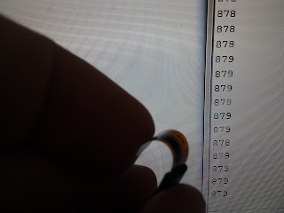
  • Using a voltage divider by Phidgets and an Arduino Duemillenove I was able to get a resolution of 800 points
  • There is a slight memory effect. If the sensor is bent very strongly it does not go back to baseline
  • The sensor is not strictly biderectional as about 80% of the possible readings are produced by flexing it in one direction. However there is enough resolution to do coarse bidirectional readings.

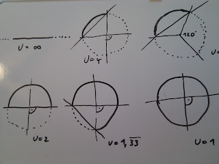
I decided to figure out the sensitivity at different levels of flexion (is that a word?) and came up with a chart that I wanted to test:
(U --> Umfang --> Circumference)

Basically I am using the sensors length as a measure and am wrapping it around an object 4 times, 3 times, 2 times and identical to the sensors length. That corresponds to distances of ∞,  2.26,  2.1, 0.777 & 0 inches (I dident do 1,33)

I used a phidgets voltage divider set to 27.4k and the analogue in of my Arduino for these measurements. These are the values I got:
  • Baseline ~ 725 when first connected,  710 after beeing bent strongly and released again
  • 4x -- ~ 550
  • 3x -- ~ 450
  • 2x -- ~ 290
  • Circle ~ 80
I also drew a linear scale, moving the two ends closer together by half an inch at a time:
  • 3"    --  ~ 710
  • 2.5" --  ~ 420
  • 2"    --  ~ 280
  • 1.5" --  ~ 180
  • 1"    --  ~ 120
  • 0.5" --  ~  80
While there is a slight memory effect (i.e. my reasings are lower after having flexed it once) the readings where constant and repeatable after that.

I measured it by marking the distance I want to bend (or flex) to and holding one end tight moving the other end to that mark:


The sensor is glued to a strip of plastic for a more rigid setup. This is to minimize rotation or uneven flexing of the sensor. Which brings me to the main drawback of the 3" sensor: As it is so long, the flexing can happen at different places and it is also prone to rotate, which severely influences the readings. For very precise sensing, it may be of benefit to use shorter sensors.

Here are some images of the 3" sensor in action:


The 2" sensor seems easyer to work with than the 3" sensor, as it is less prone to multiple bends or rotations which give readings which are hard to interpret. My favorite, was the 1" sensor. To be honest that one really surprised me. I got the largest range of readings from it, and becouse of its small size, the readings are very clear (its almost inpossible to bend it in two different ways at the same time, and it is really easy to avoid rotation.) here are some images of the 1" sensor in action: