
Nitinol hounts me.
But after several burns, two minor fires, one exploded LED and a fried Arduino UNO I decided to abandon it for now. (Dont ask. I am clumsy some times...)
Instead I stumbled upon a simple but intreaguing origami folding pattern which enables motor actuated animation. I turned it into what will be our final project for coca201. The mechanics behind it, the coding, everything, is very, very simplistic. But its beautiful and I am happy about it. Take a look:
The interesting part of this is that you have paper animation as input and output.
More videoclips of the birds are here
http://www.youtube.com/watch?v=yc6EwgwI9uw
http://www.youtube.com/watch?v=BW7r0lj5CL0
*
Now, I actually am really sad about letting the nitinol be. I guess I should just get myself some propper relays and do the math and do it the propper way... but maybe another time. Also, Cameron created a really nice Max Patcher for handling projection on a moving surface...
You can take a look at this - unfinished - project here:
Posts mit dem Label stretch sensor werden angezeigt. Alle Posts anzeigen
Posts mit dem Label stretch sensor werden angezeigt. Alle Posts anzeigen
Mittwoch, 30. März 2011

Sonntag, 27. Februar 2011
RaibowCoat - ShadowCoat with some Color :-)
Take a look :-D
And some stills:


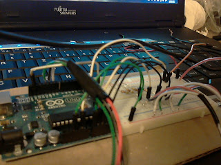
And my arduino and breadbord, which powers all of this:

And some stills:


And my arduino and breadbord, which powers all of this:


Mittwoch, 23. Februar 2011
ShadowCoat v 0.02
Before I start rambling, take a look at this video. It’s a demonstration of how the prototype I built can be used as an interface device. I am here demonstrating how it could be used as a mouse. It’s sort of cool, though it sort of takes something really cool and turns it into something banal. While this works, and I know I can get it to work a lot better still, I am hoping to find more intuitive and natural ways of interfacing with computers using this type of technology. (ah, I have already started rambling. Whatever. Watch the video-clip.)(and hear some more rambling)
While my original demo worked quite well, it didn’t have any cable management, so you can spend quite some time figuring out which cable leads where etc. Also the material was quite flimsy and I mounted the Velcro upside down which isn’t helping the material either... also, the pressure fitting was sort of annoying etc. etc. Lots of little things which could be improved.
So on my week off of university, I decided to build a new prototype. Things I wanted to include/change where
- Feedback
- Cable Management
- Tilt of wrist
- Smarter positioning of Velcro
- Sturdier material
Halfway through my work my sewing machine died on me. Well. It didn’t really die. It just sort of protested against sewing cables and electrical equipment to clothing. Guess this isn’t the future it envisioned. But it still is pretty, have a look:


Also I realized that by sheer luck I did a really good job on my first prototype. I had to figure out, often by trial and error, lots of little things which I, by pure coincidence, got right the first time I did it.
But I prevailed :-D. And while I got about half of what I wanted done, it’s a good start and I can definitely build on it, it is much more expandable/upgradeable than my first attempt.


The white thing you se protruding from my arm is an LED strip, so I can have color feedback to my movements.
One of the things which really baffled me was the voltage divider. First time round it just worked, so I didn’t spend much thought or time on it. This time I was not so lucky. So, here is how it should be done:

It is my experience, that the resolution is best when the resistance of R2 is as close as possible to the nominal resistance of the corresponding sensor. I think it might help this project to include opamps for better resolution. I hope to be testing that soon.
I also rewrote all of my code. For the first time in my life I found myself actually appreciating how powerful object oriented programming is. It improves the simplicity of my code drastically, makes it much easier to add sensors, to scale and map them and to just generally have some useful signal flow.
I also figured out that timing is really crucial. I have never really worried about how long it takes to execute a function, but I realized that this is the reason to 90% of errors and bugs I had in my programming, as it can go haywire when the timing between serial and java as well as the communication between objects is out of sync.
Anyway, for the first time I have some code which actually works well enough, that I feel like sharing it. I will figure out the proper format of doing so as soon as I get around to it. In the meantime feel free to contact me at paul dot strohmeier at gmail.com if you would like a look at it.
*
OK, some more random pictures, just because I took them :-D

4 Voltage dividers (schematic of individual one can be found in a pic further up)

Stretch Sensor material from Images

I did this at my grandparents place. This is my gradfather workshop, where I did some soldering.

It’s hard to see, but in case you are interested in how I connected the sensor material with the wired, this sort of gives a clue. I basically just wrap the wire ends around the sensor. If I had a working sewing machine I would pin this to the canvas using criss-cross stitches. As my sewing machine preferred not to support this line of work, I just put electrical tape around it, before sewing it to the shirt by hand.
Anyway - that’s it for now. I really hope I will have time to incorporate the leds and other stuff, but I am afraid it might take a while before I find time to continue work again...
Sonntag, 2. Januar 2011
Motion Capturing with Stretch Sensor
I have not posted in a while here... anyway ... I wrote a report to wrap up everything I have done so far before I go off to Canada... I'll upload it somewhere... this here is the part that is probably most interesting for most people... (its not 1 to 1 the way it'll be in my final report, but close enough...)
Stretch Sensors
The stretch sensors I use are made of conductive plastic material which changes its resistance depending on the amount it is stretched. This material is produced by the American company Images and can be bought directly at their webshop or at shops such as the RobotShop. The material is approximately 2mm in diameter and can be stretched up to 175%.
Basically I want to capture body movement, which is induced by muscles. Muscles are linear actuators; the only movement which they can perform is expanding or contracting. This implies, that all movements of the body are measurable in terms of contracting (flexing) or expanding (relaxing) of the muscle by stretch sensors.
Basically I want to capture body movement, which is induced by muscles. Muscles are linear actuators; the only movement which they can perform is expanding or contracting. This implies, that all movements of the body are measurable in terms of contracting (flexing) or expanding (relaxing) of the muscle by stretch sensors.
Angular Movement (Elbow and Shoulder)
The axis of rotation is inaccessible which would be a problem for most sensor types. However, the fact that the attachment points vary in distance to each other (when measured around the elbow as seen in the following picture) is actually of benefit for this sensor. In the elbow the Triceps Brachii is the main muscle controlling the elbows motion and takes advantage of this very principle. The stretch sensor basically copies the Triceps motion. The following two graphs compare the stretch sensor with the flex sensor. You can see that the flex sensor requires a sliding attachment while the stretch sensor can be permanently attached due to its elasticity.

Capturing angular movement with flex and stretch sensor (sharp angle, Tricaps Brachii relaxed)

Capturing angular movement with flex and stretch sensor (blunt angle, Triceps Brachii flexed)
Rotational Movement (Rotation of upper and lower arm)
The fact that the rotational axis is not accessible is of no relevance to the stretch sensor as we are not interested in measuring the actual rotation. What is measured is the distance between the two attachment points. From this one can then make inferences on the rotation of the arm. This method works analogue to the Pronator Teres in the lower arm, which by flexing or relaxing dictates the rotation of the wrist. The following two graphs demonstrate how rotating the arm is merely a change in distance between two attachment points.

Measuring rotation with stretch sensor (Pronator Teres flexed)
Dienstag, 23. November 2010
Sewing the Stretch Sensor
I have been trying to figure out how to best connect the stretch sensors to fabric. What I did before was simply using relatively thick multi-strand cables and attaching the stretch sensor using pressure fitting. I would then just sew the multi-strand cable to the fabric.
However, the rigid plastic parts required for the pressure fitting do not especially appeal to me, they are clumsy and don’t work as well as I was hoping they would.
I was hoping to find a method of making the actual sensor more stable and making it easier to attach the sensor to clothing. I ended up sewing the sensor and cable directly to elastic bands. This works fairly well, especially as the maximum stretch of the elastic is less than that of the sensor, protecting the sensor from being overstretched. Well … enough talk, take a look at the pictures to see how this looks in practice


However, the rigid plastic parts required for the pressure fitting do not especially appeal to me, they are clumsy and don’t work as well as I was hoping they would.
I was hoping to find a method of making the actual sensor more stable and making it easier to attach the sensor to clothing. I ended up sewing the sensor and cable directly to elastic bands. This works fairly well, especially as the maximum stretch of the elastic is less than that of the sensor, protecting the sensor from being overstretched. Well … enough talk, take a look at the pictures to see how this looks in practice


Ahh… and ignore all the extra threads and sloppy craftmanship. Next-time round this will look a lot prettyer. My sewing machine and me *are* (slowly) becoming friends…
Mittwoch, 10. November 2010
ShadowCoat Mouse
I procrastinate productivly: I should have been doing other university stuff, instead I thought... "can I use my set-up as a mouse?"
Well, I gave it a shot. I'll coment more on it later.
Well, I gave it a shot. I'll coment more on it later.
Montag, 8. November 2010
Introducing: The ShadowCoat (Part 2)
As mentioned before, I have changed my approach a bit, dropping the thermoplastics and going more towards smart clothing direction. I suggest you just take a look at the video. I'll post some pictures and explanations below.
What is most noteworthy in the video is that the rotation of the arm does the two sensor thing I've been talking about (cant wait to see that work on the elbow and shoulder as well). This greatly increased the accuracy of the reading. Also, the software now out-calibrates. This makes the suit ultra-usable. A friend just tried it on and it worked as effortlessly with her as it did with me.
I am still using the stretch sensor by Images. As you can't soldier plastic, I had to find other means of connecting them to cables:


I am sewing them to the construction I prepared yesterday, you can see them in this post.


From my ShadowCoat :-) the sensors connect to voltage dividers which in turn connect to the Arduino Mega...

Here is what the whole thing (and me) look like at the moment. I'm quite happy, cause this worked better than expected :-)
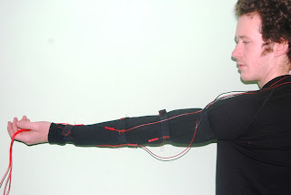


What is most noteworthy in the video is that the rotation of the arm does the two sensor thing I've been talking about (cant wait to see that work on the elbow and shoulder as well). This greatly increased the accuracy of the reading. Also, the software now out-calibrates. This makes the suit ultra-usable. A friend just tried it on and it worked as effortlessly with her as it did with me.
I am still using the stretch sensor by Images. As you can't soldier plastic, I had to find other means of connecting them to cables:


I use multi-core cables (ahh, I know thats not the correct term, but its late...), so sewing over/through/on them is no problem

I am sewing them to the construction I prepared yesterday, you can see them in this post.

I was fooling around with the readings from the stretch sensors earlier and realized, that using two sensors which counteract each other would greatly benefit accuracy and amplitude of the signal. I tried it, and yep, it works :-)

From my ShadowCoat :-) the sensors connect to voltage dividers which in turn connect to the Arduino Mega...

Here is what the whole thing (and me) look like at the moment. I'm quite happy, cause this worked better than expected :-)


Samstag, 23. Oktober 2010
Sending Data over the Network --> First Success
So I figured out that Processing has a network library. Its a step in the right direction. Raises the question weather this can be used for sending data via the Internet. Probably not. Actually, yes it can :-) But hey. One step at a time
Enjoy the clip:
Enjoy the clip:


Connecting Thermoplast to Sensors
(I will comment on these later. Right now I just want to upload these so I can fool around with some new stuff.)





Abonnieren
Posts (Atom)