
Using Beads, the DUL processing library, and my own little signal processing class:
(you may want to turn up your speakers a tad when watching this...)
There is something really beautiful about this. Cant wait to create more complex systems :-)
edit: follow this link for setup instructions --> http://fkeel.blogspot.com/2012/03/dul-radio.html
Sonntag, 11. März 2012

Samstag, 10. März 2012
WristFlicker
Somewhat over a year ago, I set out to build my "ShadowCoat".
Since then I have learned more than I ever thought I would learn about technology, art, innovation, media, AI and human computer interaction. Its been a really wild ride.
So anyway, my "ShadowCoat" never got finished as planned. However, In a downgraded version, I did end up completing my project.
The whole thing turned into WristFlicker. A motioncapture system which measures the movements of the wrist.
With great support of Audrey Girouard I managed to get it published at TEI :-)
So, here, take a look at the final version:
You can download our paper here: http://www.paulstrohmeier.info/WristFlicker.pdf
Since then I have learned more than I ever thought I would learn about technology, art, innovation, media, AI and human computer interaction. Its been a really wild ride.
So anyway, my "ShadowCoat" never got finished as planned. However, In a downgraded version, I did end up completing my project.
The whole thing turned into WristFlicker. A motioncapture system which measures the movements of the wrist.
With great support of Audrey Girouard I managed to get it published at TEI :-)
So, here, take a look at the final version:
You can download our paper here: http://www.paulstrohmeier.info/WristFlicker.pdf
DUL Radio
(scroll all the way to the bottom for a link to the code)
At TEI2012 met a group of people from Aarhus University, demoing their new little wireless board.
http://www.digitalurbanliving.dk/news/news/dul-radio.php
Its called a DUL Radio and, well... its pretty cool. They where kind enough to give me a sample, and I have been playing around with the processing library they provided. I am also writing a small signal processing library, since I have noticed that there are certain functions I tend to re-use a lot.
Both libraries are used in following video:
*
So what can these things do?
- Up to 4 green sensorBoards can connect to on receiver.
Each sensorBoard has:
- a slot for a coin battery
- One 3 axis accelerometer built in
- Two analog inputs
- One of these inputs can in future be used as a PWM output.
This gives you a total of 4 Accelerometers, 8 Analog Inputs and 4 PWM outputs for your project!
*
Below you can see the receiver board on the left, one sensor board in the middle and an xBee pro module on the right. Note that the xBee pro does not have an accelerometer built in, nor does it come with its own powersource. Oh, and the DUL radio is much easyer to use :-)

 Just comparing their size with an arduino
 And a closer look...
(thanks to Johanna Rannula for taking the pictures)
*
So how do you get these to work?
To clarify how simple this is: My biggest problem with getting this set up was, that I did not realize how easy it is. Becouse of this, I tried solving problems which did not exist.
So, for windows 7, 32bit, this is what you do:
a) Install driver
Its not completely obvious where in that zip it actually is. This is the correct path:
AT90USBnRF-AT90USB162-usbdevice_cdc_rf-1_0_0-doc\...
...AT90USBnRF-AT90USB162-usbdevice_cdc_rf-1_0_0-doc\...
...demo\...
...AT90USBnRF-AT90USB162-usbdevice_cdc_rf\
I also had a wierd issue with my file encryption. When I tried to install the driver, I was told that "Access is Denied". I figured out that it was some wierd encryption issue. If you have that problem as well, you can solve it by:
RightClick on folder / General / Advanced / uncheck "encrypted" and apply to all folders
b) Do something with it
It appears, that the software of choice for interfacing with the DUL radio is Cycling74s Max/MSP/Jitter. If you are like me and graphical programming frustrates you, then you might want to check out their processing library:
http://dl.dropbox.com/u/350755/DULRadio.zip
How to install the library:
The library is still under development, so its sort of bumpy. The most important thing to realize is that dul.getDULData() returns an array of the datatype Object. You need to "cast" it into integers in order to work with it.
The way it is done in the example did not work for me. What I had to do is this:
all the sensor data is now in the values array and should be easy to work with.
*
If you have any questions e-mail me. You can download the code here: www.paulstrohmeier.info/DUL_Processing.zip
p.
At TEI2012 met a group of people from Aarhus University, demoing their new little wireless board.
http://www.digitalurbanliving.dk/news/news/dul-radio.php
Its called a DUL Radio and, well... its pretty cool. They where kind enough to give me a sample, and I have been playing around with the processing library they provided. I am also writing a small signal processing library, since I have noticed that there are certain functions I tend to re-use a lot.
Both libraries are used in following video:
*
So what can these things do?
- Up to 4 green sensorBoards can connect to on receiver.
Each sensorBoard has:
- a slot for a coin battery
- One 3 axis accelerometer built in
- Two analog inputs
- One of these inputs can in future be used as a PWM output.
This gives you a total of 4 Accelerometers, 8 Analog Inputs and 4 PWM outputs for your project!
*
Below you can see the receiver board on the left, one sensor board in the middle and an xBee pro module on the right. Note that the xBee pro does not have an accelerometer built in, nor does it come with its own powersource. Oh, and the DUL radio is much easyer to use :-)


(thanks to Johanna Rannula for taking the pictures)
*
So how do you get these to work?
To clarify how simple this is: My biggest problem with getting this set up was, that I did not realize how easy it is. Becouse of this, I tried solving problems which did not exist.
So, for windows 7, 32bit, this is what you do:
a) Install driver
- - Download it:
- - Plug in the receiver
- - go to Device Manager
- - find Bootloader & Gateway USB Stick
- - click Update Driver Software
- - click Browse My Computer For Driver Software
Its not completely obvious where in that zip it actually is. This is the correct path:
AT90USBnRF-AT90USB162-usbdevice_cdc_rf-1_0_0-doc\...
...AT90USBnRF-AT90USB162-usbdevice_cdc_rf-1_0_0-doc\...
...demo\...
...AT90USBnRF-AT90USB162-usbdevice_cdc_rf\
I also had a wierd issue with my file encryption. When I tried to install the driver, I was told that "Access is Denied". I figured out that it was some wierd encryption issue. If you have that problem as well, you can solve it by:
RightClick on folder / General / Advanced / uncheck "encrypted" and apply to all folders
b) Do something with it
It appears, that the software of choice for interfacing with the DUL radio is Cycling74s Max/MSP/Jitter. If you are like me and graphical programming frustrates you, then you might want to check out their processing library:
http://dl.dropbox.com/u/350755/DULRadio.zip
How to install the library:
- - Find your Processing Sketchbook
- - Find or create a folder "libraries" in your sketchbook
- - Create a folder called DULRadio and copy the content of the zip file there.
The library is still under development, so its sort of bumpy. The most important thing to realize is that dul.getDULData() returns an array of the datatype Object. You need to "cast" it into integers in order to work with it.
The way it is done in the example did not work for me. What I had to do is this:
int[] values = new int [4]; //create an int array for storing your data
// request data from the DUL radio
objData = dul.getDULData();
//use this to see the values which are coming in, prior to any manipulation:
println(objData);
//parsing objData
if (objData != null) { //only do this if there is data to work with
for (int i = 0; i < values.length; i++){
values[i] = (Integer) objData[i]; //cast the Objects as Integers
}
}
all the sensor data is now in the values array and should be easy to work with.
*
If you have any questions e-mail me. You can download the code here: www.paulstrohmeier.info/DUL_Processing.zip
p.
Donnerstag, 1. März 2012
ProjectionArt @ TEI2012
Tuesday was the day of meal and gathering at TEI. And apparently there was plans to project 'something' on the ceiling. Just nobody knew what.
So about 30 minutes before the banquet opened I was asked if I had something to project. I had been playing with the ESS library for processing and through something together in ~10 minutes.
Its simply two rows of white stripes which react to sound recorded through the microphone. But it looked fairly decent (sadly the pictures only show about two thirds of it) and people started interacting with it while waiting for their meal.


So about 30 minutes before the banquet opened I was asked if I had something to project. I had been playing with the ESS library for processing and through something together in ~10 minutes.
Its simply two rows of white stripes which react to sound recorded through the microphone. But it looked fairly decent (sadly the pictures only show about two thirds of it) and people started interacting with it while waiting for their meal.


Thanks to Marty for the images :-)
Samstag, 18. Februar 2012
TEI2012 & New Website
All excited about TEI tomorrow. Will be presenting a paper, an art exploration as well as a submission to the design competition. :-)
Also, I now have a website.
www.paulstrohmeier.info / www.11235.info
check it out :-)
Also, I now have a website.
www.paulstrohmeier.info / www.11235.info
check it out :-)
Freitag, 15. Juli 2011
DIY Flexible Circuits
I am currently creating flexible circuits for a project I am working on. How to create your own flexible circuit is well documented:
http://www.instructables.com/id/DIY-Flexible-Printed-Circuits/#step1
The etching instructions I followed can be found here:
http://www.instructables.com/id/Stop-using-Ferric-Chloride-etchant!--A-better-etc/
For my project however I need multiple layers and I also need to integrate several IC's with many small pins. First I figured I would have to get it printed profesionally, however I ended up giving it a shot, with surprisingly good results.
Flexible Circutis & IC's
To test whether this was feasable I decided to create small brakout boards for a multiplexer and an atmega. I managed to get a friend interested in this, so together with Marty I designed some simple 1 to 1 pin breakouts for the two ICs.

Here you can see the two circuits printed on pyralux using a solid state printer. I designed them using Inkscape (http://inkscape.org) a freewhere program which turned out astoundingly powerful and userfriendly.
Below are two images from the etching process.


Once out of the etching solution and cleaned we went about soldering the components. Neither of us had any Idea on how to actually do this, however this sparkfun tutorial gave me some confidence that it was actually possible: http://www.sparkfun.com/tutorials/36


This is what I learned:
- make sure that your circuit design and the IC line up perfectly. When designing your circuit make sure that the footprint is as close to the actual area touched by the feet of the IC. Making them a lot bigger or smaller would make it a lot more difficult to solder.
- make the leads as thick as possible. If they are thinner than 1mm they are very easy to tear off the plastic base.
- tin the connecting elements and some of the surrounding circuitry. Cover it in a thin layer of solder
- glue the circuit in place. We used spray glue. You can use any glue, but make sure that it does not push the circuit up. We first tried a crumbled bit of scotch tape, but that messed things up badly. Ideally the circuit should be glued down well enough to connect the circuit even without soldering.
- very quickly push the feet down with a HOT soldering iron. If the iron is hot enough, the connecting leads will heat up and the solder will flow toward the feet of your IC. You dont need a lot of solder to make a connection. If the iron is not hot enough, this does not work and it gets messy.
- once all your feet are connected in a satisfying manner use soldering wick (http://www.sparkfun.com/products/8775) to clean it all up a bit. If you have solder bridges it is usually sufficient to place it on the lead near the bridge, the solder will then flow towards the lead. In theory, once you have connected the IC to the circuit you never have to bring it back in contact with the soldering iron, minimizing your risk of burning it up
Once all that was done I soldered on some pinheaders and stuck the whole thing in a breadboard:


To make sure that I did not fry anything, I compared it to the breakoutboard by sparkfun

Aside from the fact that our little board is transparent, flexible and just overall more charming and lovable than the sparkfun version it performed identically. I think it might have been slightly noiser, but that could also just have been me not believing that it would perform equally well....
Multi-Layerd Flexible Circuits


.
http://www.instructables.com/id/DIY-Flexible-Printed-Circuits/#step1
The etching instructions I followed can be found here:
http://www.instructables.com/id/Stop-using-Ferric-Chloride-etchant!--A-better-etc/
For my project however I need multiple layers and I also need to integrate several IC's with many small pins. First I figured I would have to get it printed profesionally, however I ended up giving it a shot, with surprisingly good results.
Flexible Circutis & IC's
To test whether this was feasable I decided to create small brakout boards for a multiplexer and an atmega. I managed to get a friend interested in this, so together with Marty I designed some simple 1 to 1 pin breakouts for the two ICs.

Here you can see the two circuits printed on pyralux using a solid state printer. I designed them using Inkscape (http://inkscape.org) a freewhere program which turned out astoundingly powerful and userfriendly.
Below are two images from the etching process.


Once out of the etching solution and cleaned we went about soldering the components. Neither of us had any Idea on how to actually do this, however this sparkfun tutorial gave me some confidence that it was actually possible: http://www.sparkfun.com/tutorials/36


This is what I learned:
- make sure that your circuit design and the IC line up perfectly. When designing your circuit make sure that the footprint is as close to the actual area touched by the feet of the IC. Making them a lot bigger or smaller would make it a lot more difficult to solder.
- make the leads as thick as possible. If they are thinner than 1mm they are very easy to tear off the plastic base.
- tin the connecting elements and some of the surrounding circuitry. Cover it in a thin layer of solder
- glue the circuit in place. We used spray glue. You can use any glue, but make sure that it does not push the circuit up. We first tried a crumbled bit of scotch tape, but that messed things up badly. Ideally the circuit should be glued down well enough to connect the circuit even without soldering.
- very quickly push the feet down with a HOT soldering iron. If the iron is hot enough, the connecting leads will heat up and the solder will flow toward the feet of your IC. You dont need a lot of solder to make a connection. If the iron is not hot enough, this does not work and it gets messy.
- once all your feet are connected in a satisfying manner use soldering wick (http://www.sparkfun.com/products/8775) to clean it all up a bit. If you have solder bridges it is usually sufficient to place it on the lead near the bridge, the solder will then flow towards the lead. In theory, once you have connected the IC to the circuit you never have to bring it back in contact with the soldering iron, minimizing your risk of burning it up
Once all that was done I soldered on some pinheaders and stuck the whole thing in a breadboard:


To make sure that I did not fry anything, I compared it to the breakoutboard by sparkfun

Aside from the fact that our little board is transparent, flexible and just overall more charming and lovable than the sparkfun version it performed identically. I think it might have been slightly noiser, but that could also just have been me not believing that it would perform equally well....
Multi-Layerd Flexible Circuits
This was surprisingly simple. To connect a small matrix of sensors I simply designed the layers seperatly. Then I made holes in the top when where they where required and soldered in the sensors. Kaboom. Magic :-D

top layer with holes

bottom layer

both layers together

both layers with sensors mounted
Anyway. Thats it for now. I will be working on this stuff for a while now and will report back with any further insights I might have. While I am doing so - does anyone have any further suggestions? Any secret tricks you use when creating your circuits?
Anyway
Thats it for now.
Cheers
p.
.
Sonntag, 26. Juni 2011
Ribbon Cables - Arduino Cable Management
EDIT: For the record: DONT do this. Unless you are on a super, super, super tight budget, buy these:
http://www.pololu.com/catalog/category/71
together with these:
http://www.pololu.com/catalog/category/70
Seriously. Make life soooo much easyer.
************************
I stumbled across John Liu's Phi Connect and loved everything about it, except that he doesnt have an Arduino Mega version.
check it out: http://liudr.wordpress.com/gadget/phi-connect/
*
I am prototyping a lot with the Arduino Mega at the moment, and I wanted to improve my cable management, so this is what I came up with.


I have 24 leads connected. 8 go to analog in 0 - 15, 4 go to digital 2 - 7 (as I dont use pin 0 & 1 anyway...) which leaves me with a power and ground cable. works very nicely for me, especially as my actual application has to be semi-independent of the arduino.
If anyone plans on doing this for themselves, here is how I ended up doing it.
a) Prepare the wire


After crimping them, I put a ton of solder on both the cable and the pinheader.
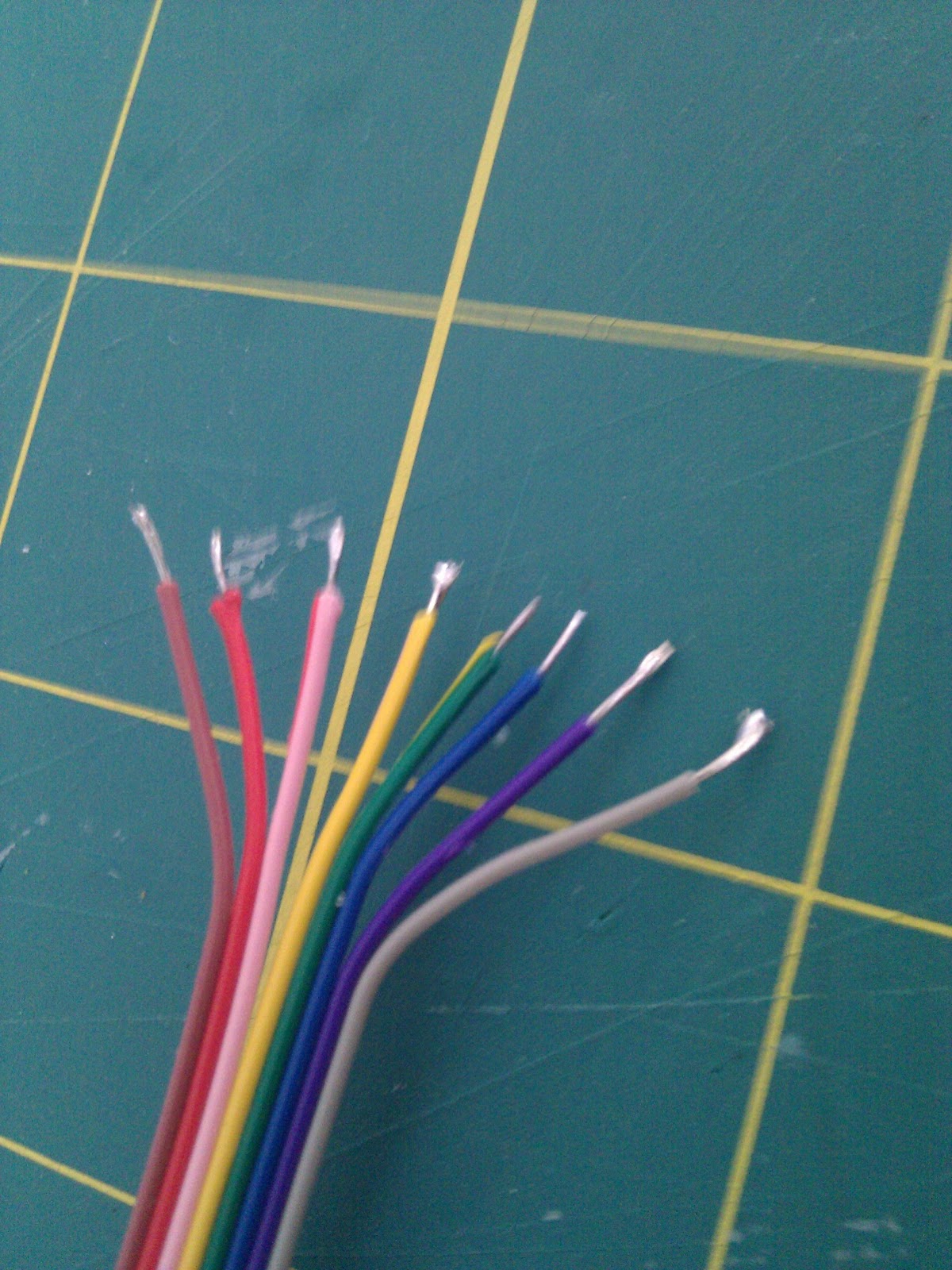
Soldering the pinheader is a real pain. The stuff just wont stick to it, and if you fool around too much you start melting the plastic and the pins get loose/crooked etc.

Its inportant however, becouse once thats done, you can just push them together with your soldering iron. Your other hand will be free, as you dont need to add anymore soder, so you can use it to make sure the cable and the headers line up perfectly. If you bend the cable in the right shape, and apply the right amount of solder beforehand you can solder several leads at the same time... after doing this a couple of times you learn how to do it quite efficiantly.
Once it was done I made sure that there where no connections between the cables, wrapped it up with electrical tape and thats all there is to it.


It was more work than I had anticipated ... but assuming they last me for a while, its definitifly worth it.
Abonnieren
Posts (Atom)